NodeIT ESP8266 controller board with onboard USB
Sold by ILabs Electronics
$8.31
No tax for United States [change]
General Information
The ESP-210 is a ESP8266 based module with a USB transceiver, 3.3V voltage regulator (you can run it from 5v or the USB port) and a 32MBit (that is 4 MByte !!) FLASH memory. Unlike many other ESP8266 based modules this module comes prepared for anyone that wants to tinker and play around with it without having to connect external adapters and power supplies to it. In fact, to start playing with it you only need to plug it in to your computers USB port. The device will take all of its power from the USB port. The ESP-210 also has a user defineable LED on the board so you can start of by running your first blink test.
On Board USB transceiver
The ESP-210 includes a Silabs CP2104 USB to serial transceiver with TX and RX connected to the ESP8266 device. The outputs of the CP2104 are defined as open collector and have an internal weak pull up. This allows you to use the RX/TX signals of the ESP8266 freely in your application. The CP2104 will not interfere when not used. The same applies to the RTS and DTR signals which are connected to the ESP reset and GPIO0 respectively. Actually when the device is not connected to a USB host it is not even powered on, making it possible to run the unit in very low power applications.
The CP2104 allows you to load firmware into the ESP8266 with speeds up to 921600 baud. This drastically reduces the time it takes to flash the ESP-210 and when doing heavy development work this is a really nice to have feature. The module supports up to 430800 baud standalone and if you want to have the full 921600 bauds you need to connect a strong (4.7Kohm) pull up (to 3.3Volt) resistor to pin GPIO3.
Power
The ESP-210 can be powered in a few different ways, here's a list of the different options:
- USB, when powered by USB the internal voltage regulator generates the required 3.3Volts.
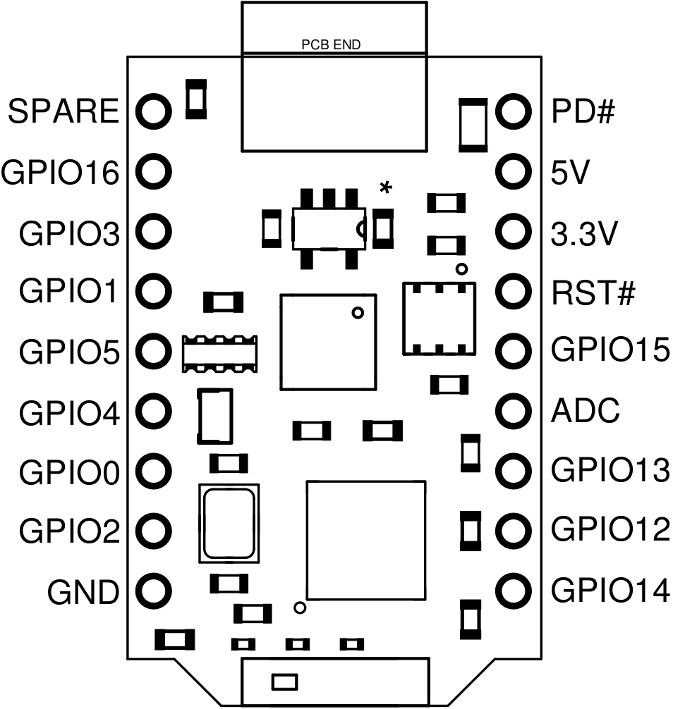
- Pin 17 (5V), This pin can be used to supply the ESP-210 with +5V. This pin is also connected to the VUSB (through a zero ohm resistor) so be careful not to exceed 5V when having it connected to a USB port at the same time. If the ESP-210 never gets connected to a USB port this pin can handle up to +7.5Volts.
- Pin 16 (3.3V), When the ESP-210 is powered by a USB cable or by pin 16 this is an output containing +3.3Volts. This pin can also be used to supply the ESP-210 with +3.3Volts. The supply must be +3.3Volts ±5% and the on board voltage regulator must be disabled by pulling the PD# pin low.
When the ESP-210 is powered through USB or Pin 17 it will get slightly warm. This is as it should be and comes from the on board linear voltage regulator.
GPIO
GPIO16 and GPIO2 both have a 4.7 Kohm pull up resistor connected to them allowing you to use them directly to connect DS18B20 temperature sensors. Keep in mind though that the I/O's are still 3.3V only.
The board has an on board blue LED that is connected to GPIO5. The LED is controlled using normal logic, i.e. setting the port to 1 (HIGH) will light the LED and setting it to 0 (LOW) will turn the LED off.
Pinout

Connectors
The module is shipped with 2 9-pin connectors that need to be soldered to the PCB. These connectors are designed to enable stacking of NodeIT-modules on top of each other.
Technical Specifications
- 32-bit 80mhz microprocessor
- 802.11 b/g/n Wi-Fi radio built-in
- 4MB of Flash, 80 KB RAM (~40 KB available for user code)
- 11 Digital I/O Pins (interrupts on 10 digital pins)
- 1 Analog Pin (Analog input 0 - 1Volt)
- PWM on all Digital Pins (up to 6 active at a time)
- Sleep and Deep Sleep modes for low power usage
- Ability to read the voltage of its power source (for battery monitoring)
- Board dimensions: 27.5mm) x 17.5mm
- Serial Speeds up to 921600 Baud
- Internal Voltage Regulator: 3.3V max 800mA
- On board full speed USB transceiver
Links to code and documentation
Shipping policy
We normally pack items on Mondays and leave them at the post office on Tuesdays. Orders received after 12:00 (CET) on Monday will be shipped the following week.

